Model |
R27 HE |
R27 RE |
R27 mk2 |
| Headphone Amp | Yes | Yes | Yes |
| Preamplifier function | Yes | Yes | Yes |
| DAC Type | Discrete R2R | Discrete R2R | Discrete R2R |
| Amplifier Type | Discrete Balanced | Discrete Balanced | Discrete Balanced |
| Regenerative Power Supply | Yes | Yes | No |
| Step Down transformers | Yes | No | Yes |
| Gain Modes | L mode : +13DBH mode : +26DB | L mode : +13DBH mode : +26DB | L mode : +13DBH mode : +26DB |
| Preamp Variable output | 20V Balanced | 18V Balanced | 18V Balanced |
| Headpone output | 25 ohm: 15W | 25 ohm: 10W | 25 ohm: 15W |
| Master Clock Input | Yes, 50 or 75 ohm | Yes, 50 or 75 ohm | Yes, 50 or 75 ohm |
| Remote Control | Aluminium Remote | Aluminium Remote | Aluminium Remote |
| Color Enclosure | Silver / Black | Silver / Black | Silver / Black |
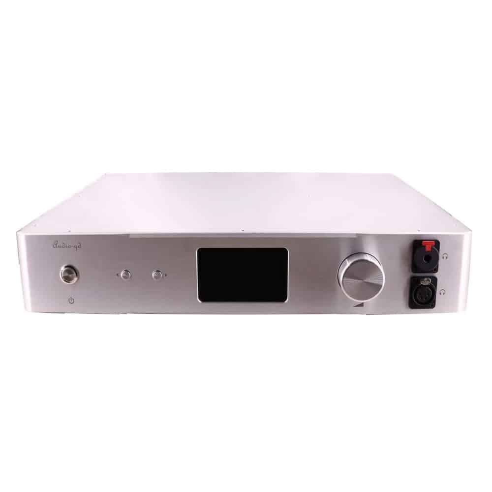
| Size | W430 X L480 X H123 | W430 X L445 X H80 | W430 X L445 X H80 |
| Weight | 24kg | 12kg | 12kg |
| Power Consumption | 53Watt | 42Watt | 32Watt |
HIGHLIGHTS
- USB fully integrated and Isolated with internal FPGA deriving clocks from Accusilicon’s (similar to DI20 architecture)
- I2S HDMI isolated input
- IN2 coaxial input accepts external 10MHz clock input ( 75 ohms )
- Firmware up gradable design
- True balanced design, discrete push-pull R2R DAC design
- Improved clock timing of internal master clock regeneration.
- Discrete analogue output stages
- DC coupled design (No capacitors in signal path)
- Non- feedback ACSS analogue output control
TECHNICAL SPECIFICATIONS
| specifications tested by OS8 mode and already through sound tuned, we always improve for better real like , musical and analog sound ,improvement may result in changes in specifications and design without notice. | ||
| S/N Ratio | >120DB | |
| THD+N | <0.03% | |
| Gain | L mode : +13DBH mode : +26DB | |
| Channels imbalance | < 0.05DB | |
| Frequency Breadth (Whole unit) | 20Hz – 20KHz (< – 0.25DB)20Hz – 150KHz (< – 3DB) | |
| Output Level | Preamp Variable output : 18V max (XLR) / 9V max (RCA)DAC Fixed output : 2-5 V (XLR) /1-2.5V ( RCA) | |
| Headphone amp Output Power (Balanced class A ) |
25 ohm: 15W 40 ohm: 10W 100 ohm: 4W 300 ohm: 1350mW |
|
| Headphone amp Output Power (Single-ended class A ) |
25 ohm: 4W40 ohm: 2500mW100 ohm: 1000mW
300 ohm: 350mW |
|
| Digital Input Sensitivity | 0.4-1 Vp-p(75 Ohms, Coaxial)19 dBm (Optical) | |
| XLR input impedance | XLR : 94K ohm | |
| Support Operate Systems (USB) | Windows, OSX, Linux, ISO | |
| Support Sampling | USB & IIS : 44.1kHz – 384kHz /32Bit DSD64-512AES/EBU and Coaxial mode: 44.1kHz – 192kHzOptical mode: 44.1kHz – 96kHz |
|
| Power Requirement | 1 Version 100-120V AC 50/60 Hz2 Version 220-240V AC 50/60 Hz | |
| Power Consumption | 42W | |
| Package Weight | Approximately 12kg | |
| Dimensions | W430 X L445 X H80 (mm) | |
| Accessories | AC power cord X1 USB cable X1 Metal remote X1 |
|
R-2R LADDER DAC
The R-2R DAC has become popular and was originally designed long time ago by MSB, and did not include the wonderful correction design of the modern MSB technology. In the High-End of the shelf (finished products) market, the R2R design is usually much more complex when outstanding performance is offered. Some manufacturers are using shift registers design to realize ladder compensation. A less complex, unfortunately also a less performing.
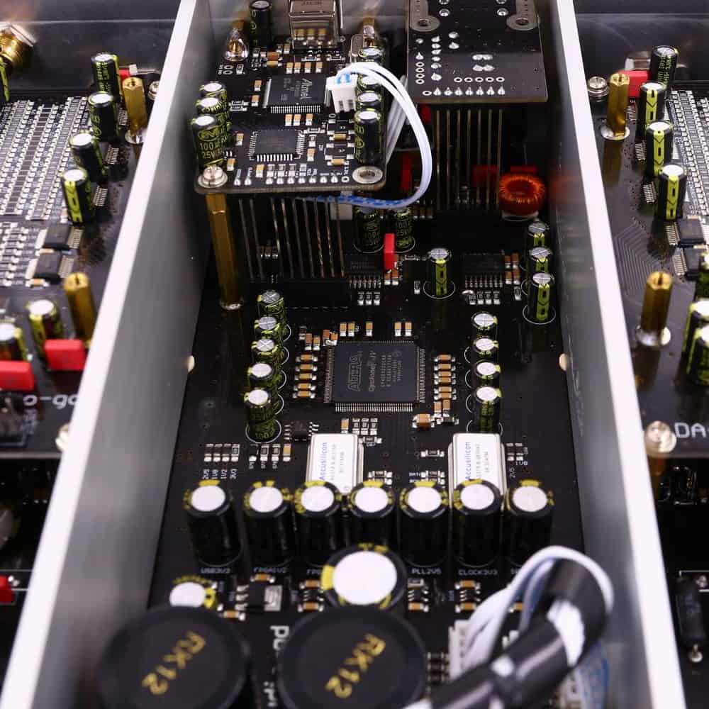
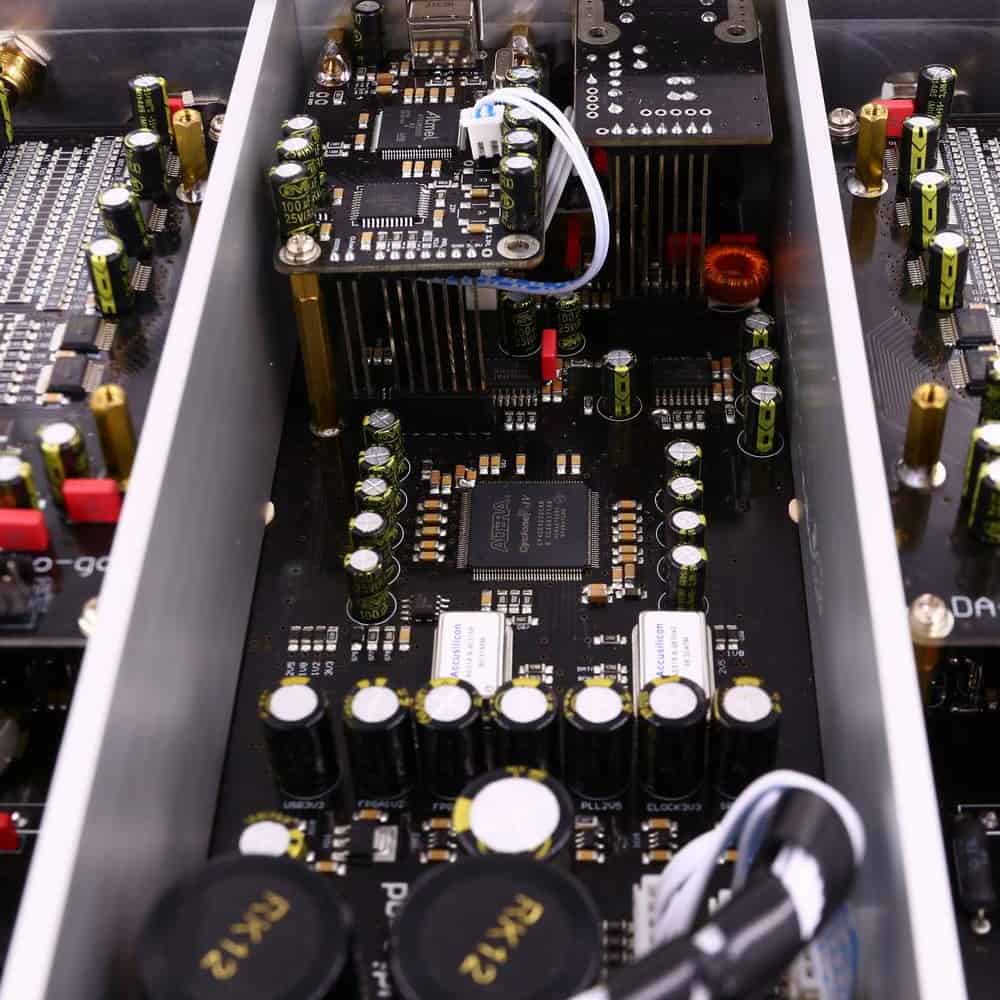
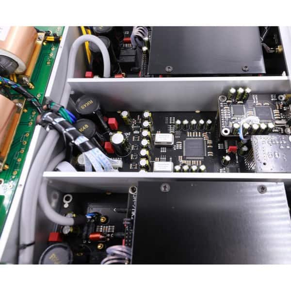
A far better design switches resistors in parallel mode; an ultra-fast FPGA chip controls and corrects the R2R ladder. The parallel design mode controls every bit respectively and therefore achieve unprecedented performance. (In parallel mode only 1 clock cycle is needed to output all data; serial design mode needs at minimum 8 up to 24 clock cycles) The parallel design is particularly complex, however when it is done properly it can correct every bit of the ladder. (Photo below shows a FPGA design with R2R ladder). With incredible speed and accuracy the R-28 will correct the unavoidable imperfections of the basic R2R ladder caused by tolerance of resistors; avoid glitches at ultra-high speed to deliver unrivaled musical performance.
ANALOGUE OUTPUT STAGES
The analog output stages are as important, they have a tremendous influence on the final sound quality. After d/a conversion by the R2R D/A modules the analogue signal is transported by fully discrete matched-transistor output stages; DC-coupled design with first class through-hole components. No SMD components are applied in the analogue section. The high speed unique ACSS ((Audio-gd Current Signal System) output stages are non-feedback and current driven. Unique performance because almost all other designs need to convert the signal multiple times from and to current and/or voltage, resulting in less detailed and less transparent sound-stage The output buffers are single ended FET; two stages in parallel to reach very low output impedance. All output stages are in pure class A without (negative) feedback to achieve purest and a real live sound reproduction. The 4 OPA op-amp’s are DC servos, this way no coupling-capacitors are needed and DC output is automatically biased. The listener will be presented a strikingly transparent and neutral sound.
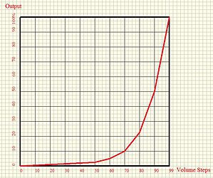
HIGH PRECISION VOLUME CONTROL
Volume control consist of relay-controlled attenuators. Fully-independent, fully-balanced stereo volume controls. The volume controls feature consist of high-precision 0.05% tolerance film resistors and golden contact relays. Buffered inputs and outputs.There 4 channels volume boards are built in the unit to achieve ultimate balanced volume control. They are controlled by a digital signal controlling the high quality relays switching the precision resistors in analog area.
 |
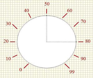 |
Quality of volume control is very important in balanced applications . It have to effectuate the four channels to work as synchronous as possible to keep the balanced signal in perfect shape. In traditional volume controls the balanced output will introduce distortion which will negatively influence sound quality and performance and might even get worse than a single ended setup and waste the advantages of balanced designed solution.
CLEAN POWER
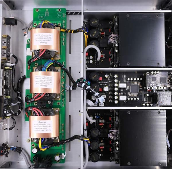
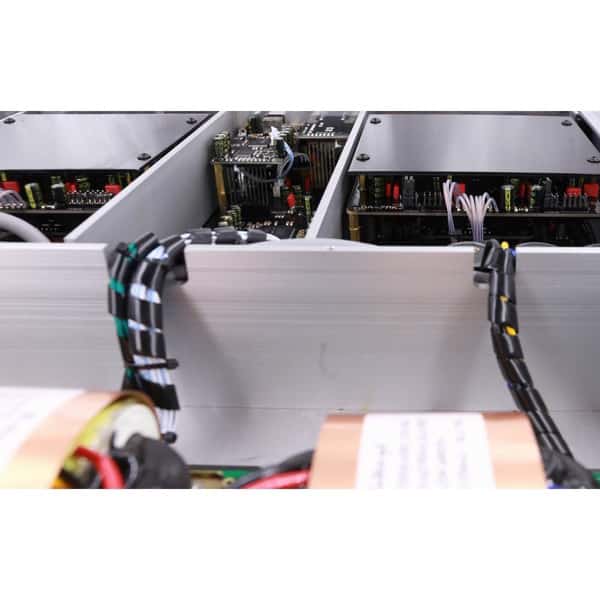
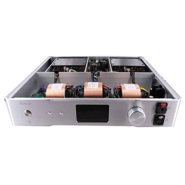
The DAC consist of 3 tuned low noise, low flux leakage, R-cores transformers. In total 130W power to supply all digital parts and the left and right analog boards. The DC power is distributed over several separate power regulators. Analogue stages are pure class A low noise shunts; fed by 3 groups linear power supplies. Resulting in ultra-high speed and clean power for all individual parts.
Đang cập nhật
Đang cập nhật









.png)
