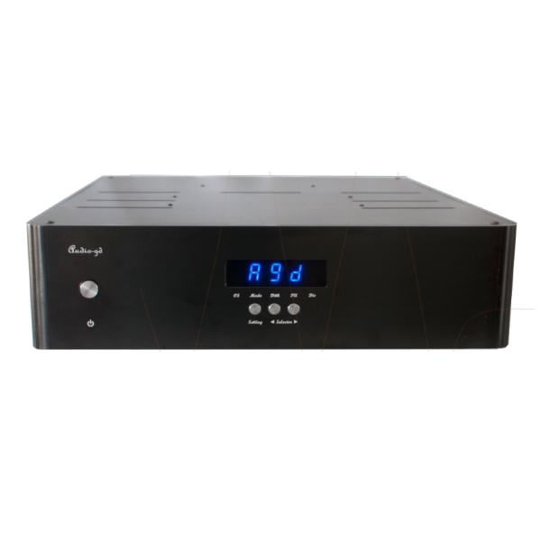
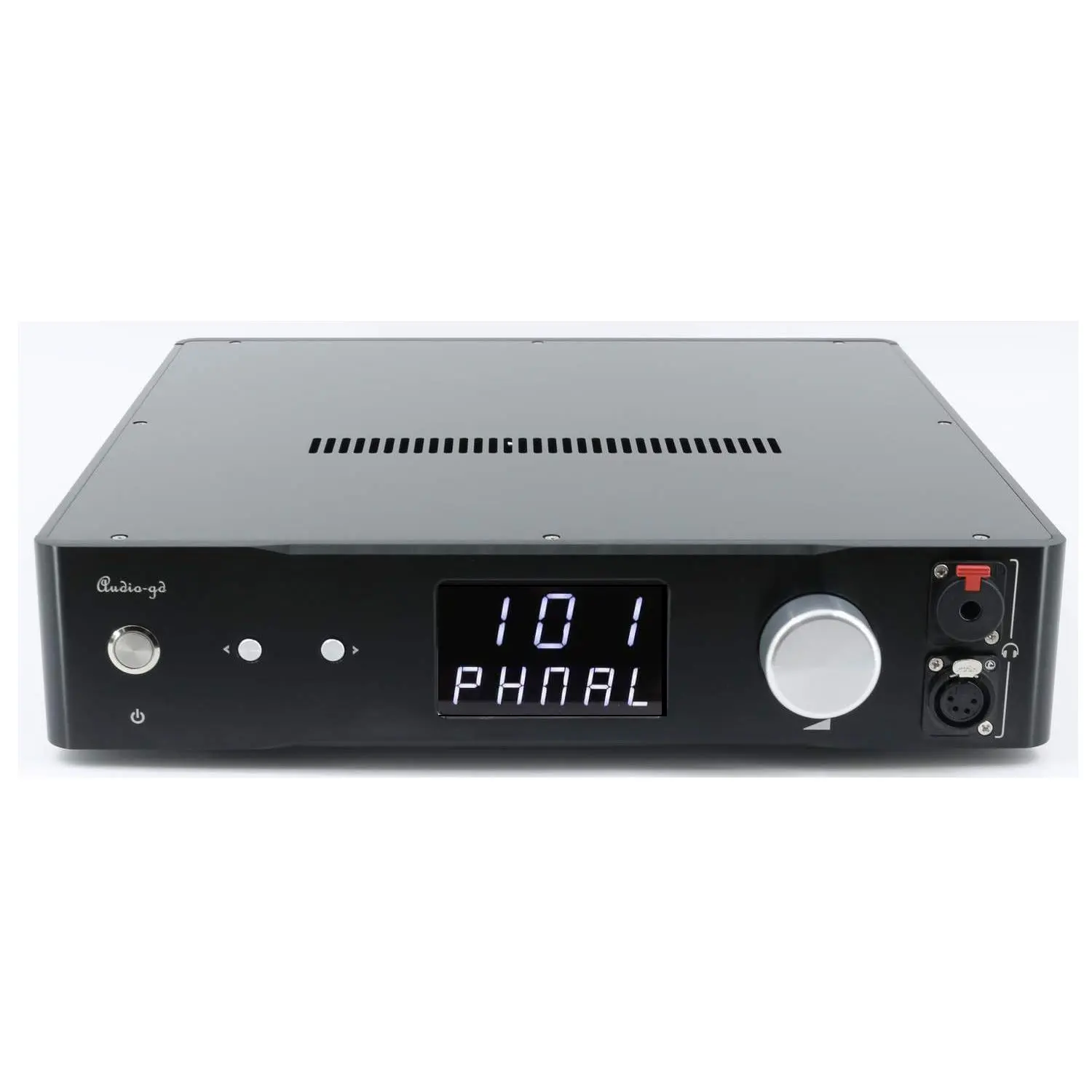
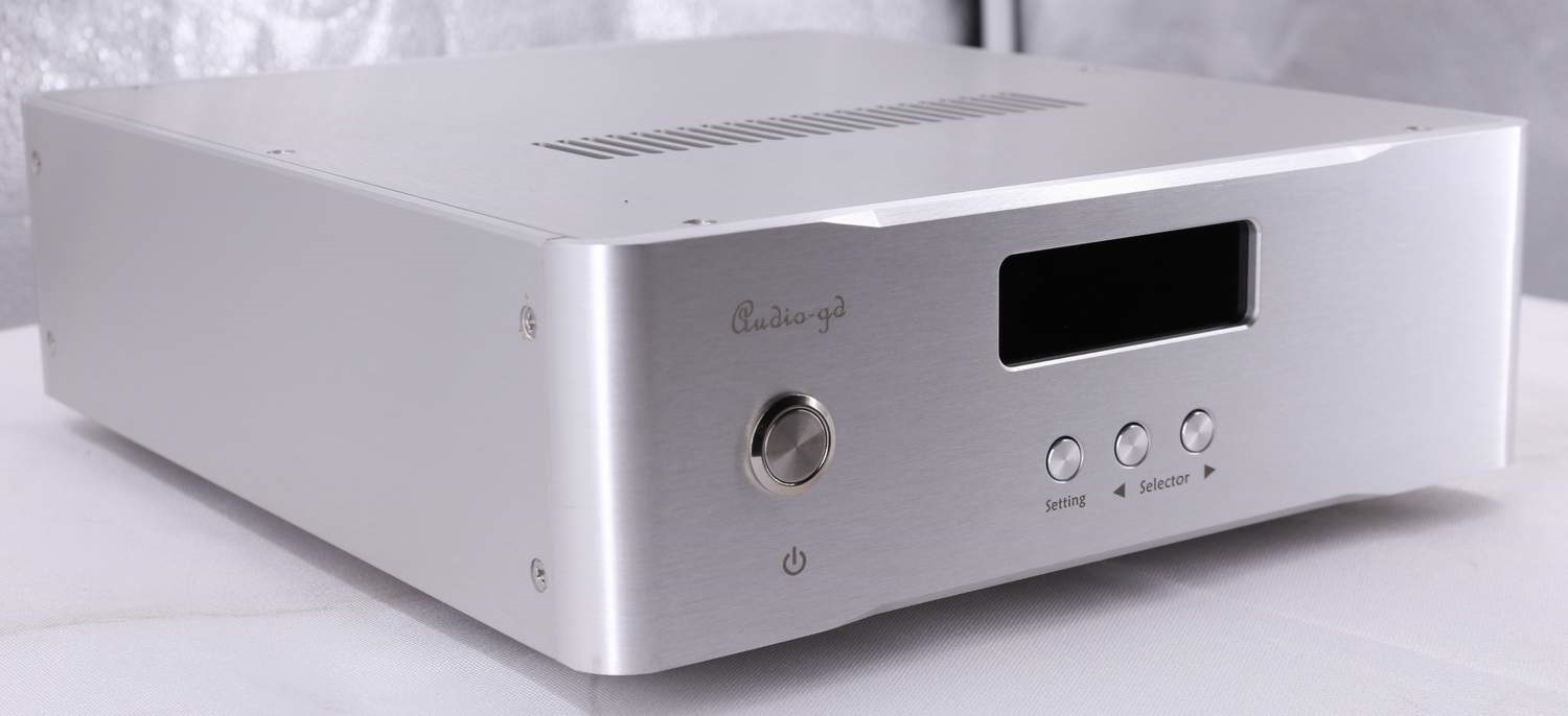
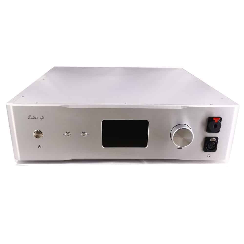
R7HE mk2 VERSION – ACCUSILICON
R-7HE MK2 HIGHLIGHTS
- Sample Rate indication for PCM and DSD on display
- USB fully integrated and Isolated with internal FPGA deriving clocks from Accusilicon’s (similar to DI20 architecture)
- Isolated HDMI input
- Dual 32 bit parallel signal processing (FPGA) on I2S / USB inputs
- Dual 24 bit parallel signal processing (FPGA) on SPDIF inputs
- DSD asynchronous clock technology (significant sound improvement)
- 10 MHz Master Reference clock input.
- The FPGA process data upgrade to parallel mode.
- Full new configuration clock manage design built in, improved on the clock timing.
- DSD asynchronous clock technology has apply that improves the sound quality obviously.
- DOP support from coaxial input .
- Micro USB Port for firmware upgrades
- Menu Mode controlled. All settings can be accessed via a menu on front.
SOUND CHARACTERISTICS
R7HE is characterized by its coherent, transparent and natural sound. Striking is the spatial sound image. Rich in detail; extremely high resolution; strong authority and wide stereo image. You’ll forget that you’re listening to a digital source.
SPECIFICATIONS |
|
|---|---|
| Product type | R2R Discrete Ladder DAC |
| SNR | > 120dB |
| Output impedance | < 5 Ohm (XLR, RCA) |
| Output level | RCA : 2.5V XLR : 5V ACSS : 2+2MA |
| Frequency response | 20Hz – 100kHz |
| Input sensitivity | Coaxial 75 Ohm : 0.5Vp-p Optical : 19dBm |
| Supported OS (USB) | Windows, OSX, Linux, ISO |
| Sampling rate | USB, I2S : 32bits 44.1kHz – 384kHz / DSD Native 512 Coaxial, Optical : 24bits 44.1kHz – 192kHz / DSD DoP 256 |
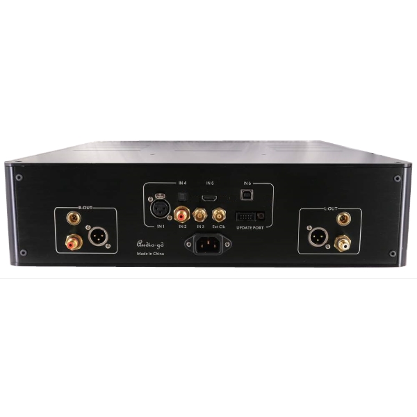
| Inputs | 1x AES/EBU XLR
1x Coaxial RCA SPDIF 1x Optical Toslink 1x I2S LVDS via HDMI 1x USB Amanero 1x 10Mhz Reference Master Clock Input 1x Micro USB Port (Firmware Upgrade) |
| Outputs | 1x Balanced ACSS 1x Balanced XLR 1x Single-Ended RCA |
GENERAL |
|
|---|---|
| Consumption | 73W |
| Dimensions | 430 x 530 x 125 mm |
| Accessories | 1x Power cable 1x USB cable |
MAGNA R2R (SILVER) UPGRADE
We, Magna Hifi, have been working for months on possible improvements for Audio-GD R2R DACs. Because we have gained a lot of experience with the Mano streamer, we had certain ideas about how things could be improved and sound better. AND IT DOES! Magna R2R Silver upgrade includes Internal board to board wiring replaced by solid core silver wiring with cotton insulation After the modification the R2R DAC sounds cleaner; and the edges will become softer better and more spacious sound image.
DIGITAL SETTINGS (OVERSAMPLING & NOS)
The R-7HE offers several Oversampling or NOS (Non-Oversampling) modes. If you wish to choose Oversampling, simply select the value “O”. If you want to choose the NOS then you have to choose the value “N”. You can then select one of the following modes to adapt the playback to your listening experience.
DSP SETTINGS |
||
Oversampling |
||
| Oversampling | Passband Filter | |
| Mode 0 | 1x Oversampling | -130dB digital |
| Mode 2 | 2x Oversampling | -130dB digital |
| Mode 4 | 4x Oversampling | -130dB digital |
| Mode 8 | 8x Oversampling | -130dB digital |
Non Oversampling (NOS) |
||
| Mode 1 | FIFO Data processing | 6dB Analogue |
| TDA1541 Emulation mode (OS 2 or 4 recommended) | ||
| *Supports -50dB passband via PLL setting | ||
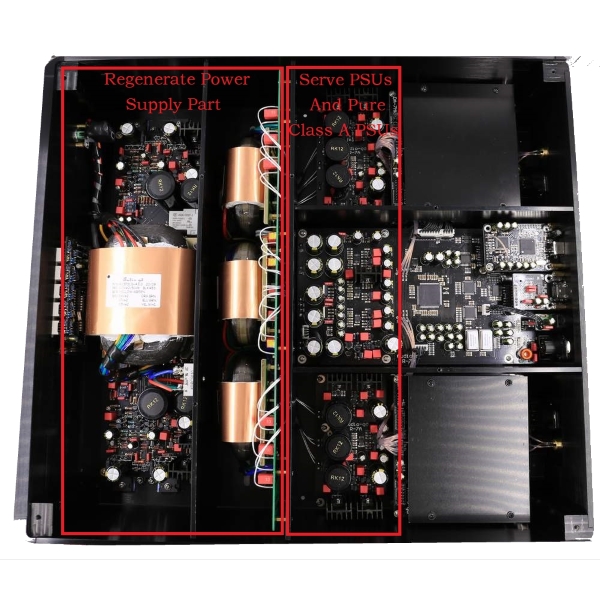
REGENERATIVE POWER SUPPLY
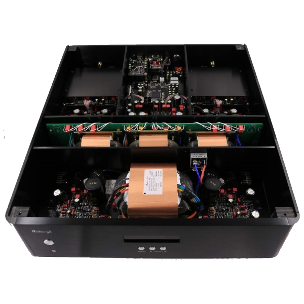
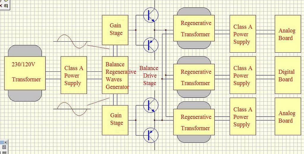
An integrated regenerative power supply is a proprietary electric generator built into the unit to avoid any noise from main power and deliver ultra-low noise and clean AC wave to feed the preamp. It will regenerate the main power and block noise from the power line, this way the preamp is able to reproduce the most neutral and analog sound you can imagine. First a transformer converts main voltage. DC conversion is done by class A PSUs power supplies.
A discrete balanced regenerative wave generator produces the new ultra-low noise wave form at 400Hz. The 400Hz frequency was chosen because they have better efficiency compared to traditional 50Hz and at this frequency, 400Hz, it will boost the sound to reproduce real and pleasant analog sound. The balanced gain amps with powerful output stages are driving the regenerative transformers to produce the extreme clean AC power. The extreme regenerated clean AC power is send to separate class A PSUs power supplies for both left and right channel. The discrete class-A DC power supply with high input impedance will avoid any noise and allow the amplifier stages to have low output impedance at very high speed and linear at frequency spectrum.
R-2R LADDER STORY
The R-2R DAC has become popular and was originally designed long time ago by MSB, and did not include the wonderful correction design of the modern MSB technology. In the High-End of the shelf (finished products) market, the R2R design is usually much more complex when outstanding performance is offered. Some manufacturers are using shift registers design to realize ladder compensation. A less complex, unfortunately also a less performing.
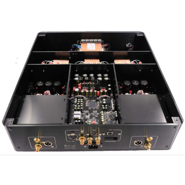
A far better design switches resistors in parallel mode; an ultra-fast FPGA chip controls and corrects the R2R ladder. The parallel design mode controls every bit respectively and therefore achieve unprecedented performance. (In parallel mode only 1 clock cycle is needed to output all data; serial design mode needs at minimum 8 up to 24 clock cycles) The parallel design is particularly complex, however when it is done properly it can correct every bit of the ladder. (Photo below shows a FPGA design with R2R ladder). With incredible speed and accuracy the R-28 will correct the unavoidable imperfections of the basic R2R ladder caused by tolerance of resistors; avoid glitches at ultra-high speed to deliver unrivaled musical performance.
TOLERANCE OF RESISTORS IN LADDER
Some manufactures claim to achieve good performance becuase they use lowest tolerance ladder resistors. The following calculation example will cover this. At 16 bit the tolerance of 1/66536, 0.1% (1/1000) it is by far not enough to achieve decent performance. Even using resistors with 0.01% (1/10000) tolerance, lowest tolerance available today,cannot deliver the desired performance This is just 16 bit, imagine a 24 calculation! To process 24 bit resolution it would require resistors with a tolerance of 0.00001%. This is purely theoretical; if this tolerance would exist the discreteness of the switch logic chips will already have too much internal impedance and will shake-up such design.The tolerance of the resistor will never solve Imperfections of a ladder.
The solution lies in the correction the ladder and not only depend on the tolerance of resistors. It’s a combination of both: Ultra-low tolerance resistors controlled by a correction technology using very high speed with parallel FPGA processing.
ULTRA FAST SIGNAL PROCESSING
FPGA stands for Programmable Array Logic. Nowadays the FPGA is widely adopted in audio devices. The internal hardware design is fully controlled by complex software. A huge advantage is the fact the software in the FPGA can easily be upgraded offering new capabilities or improve the performance of the device without replacing any hardware. Versatile and future proof design.
- High performance SPDIF interface, replacing traditional less good performing SPDIF interface chips like DIR9001, WM8805 or AK411X,etc.
- Full re-clocking process with FIFO design applicable on all inputs. This way the output data keeps fully synchronized with the clock signal to reject any jitter.
- Built in 2X, 4X and 8X oversampling and digital filters and on top of this 4 different true NOS (only analog 6dB filtering) modes. To completely configure the sound according to your taste.
DIAMOND ANALOGUE OUTPUT STAGES
The analog output stages are as important, they have a tremendous influence on the final sound quality. After d/a conversion by the R2R D/A modules the analogue signal is transported by fully discrete matched-transistor output stages; DC-coupled design with first class through-hole components. No SMD compon ents are applied in the analogue section. The high speed unique ACSS ((Audio-gd Current Signal System) output stages are non-feedback and current driven. Unique performance because almost all other designs need to convert the signal multiple times from and to current and/or voltage, resulting in less detailed and less transparent sound-stage The output buffers are single ended FET; two stages in parallel to reach very low output impedance. All output stages are in pure class A without (negative) feedback to achieve purest and a real live sound reproduction. The 4 OPA op-amp’s are DC servos, this way no coupling-capacitors are needed and DC output is automatically biased. The listener will be presented a strikingly transparent and neutral sound.
ACSS – Current Amplification
Audio-GD has developed an advanced current-driven amplifier technique. Also known as ACSS, Audio-GD Current System Signal. This special technique ensures that the signal travels a much shorter path and that ensures a more transparent, faster and more neutral reproduction. A similar technique is used by, for example, KRELL. The Current Conveyor technology mostly components are the current mirror. The Current Conveyor technology isn’t a new technology, at 1966 , professor K.C. Smith and A.S.Sedra publish the concept “current mode analogue circuits “ .
CLEAN POWER
The DAC consist of 3 tuned low noise, low flux leakage, R-cores transformers. In total 130W power to supply all digital parts and the left and right analog boards. The DC power is distributed over 19 separate power regulators. All are pure class A low noise shunts; fed by 3 groups linear power supplies. Resulting in ultra-high speed and clean power for all individual parts.
USB SUPPORT
Download USB Amanero drivers for Windows 10
Download USB Amanero drivers for Windows 7 & 8
No drivers required for Linux and/or Mac OS
OSX 10.6+ and Linux with UAC2 compliant kernel
Microsoft Windows: KS/Wasapi/WDM/ASIO
Đang cập nhật
Đang cập nhật


.png)